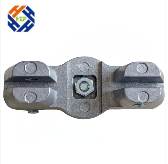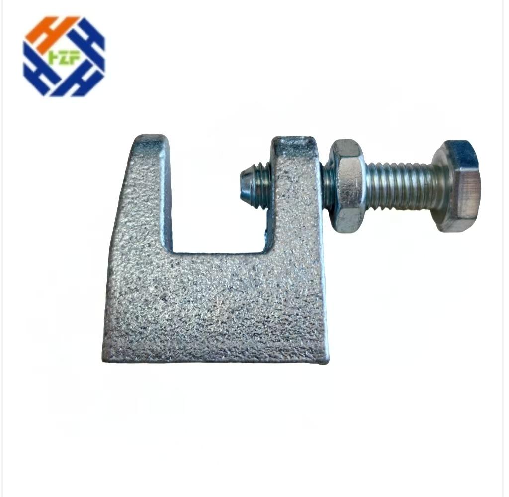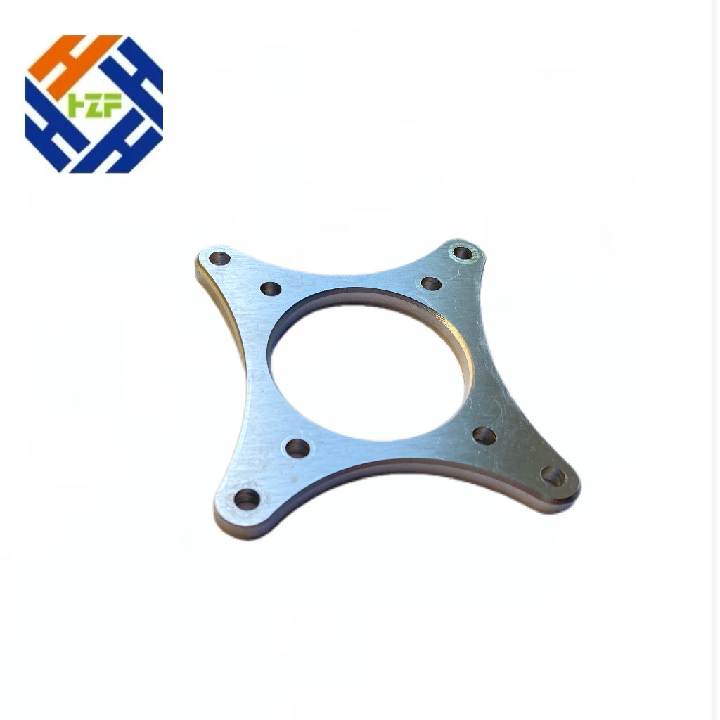
Missing drawings are a common issue in machining and equipment maintenance.Some machines have been in service for more than ten years, and replacement parts are no longer available from the original manufacturer. In other cases, a customer has an old imported component but no CAD file. Some parts were custom-made years ago, and the original supplier is no longer operating.In these situations, reverse engineering may be a practical way to recreate the manufacturing drawing. However, measuring the part and copying every dimension is not always enough.The first step is to check whether the existing part can be used as a reliable reference. If it has worn surfaces, deformation, previous repairs or modifications, the measured dimensions may differ from the original design.Machining directly from those measurements could reproduce the existing wear or dimensional errors. Before starting, it is important to understand the part's function, mounting position, loading conditions and relationship with mating components.
Not every dimension has the same importance.For brackets, mounting plates and support blocks, the main features may include hole positions, hole spacing, plate thickness and locating surfaces.For bushings, sleeves and components with bores, the inner diameter, outer diameter, concentricity and fit clearance may determine whether the part can be assembled correctly.Threaded features also require attention. The thread specification, pitch and effective depth should be confirmed rather than estimated from appearance.Engineers normally establish suitable datums first, then identify the dimensions that need to be controlled. This makes the drawing useful for both manufacturing and inspection.If the original part is worn, the mating component should also be checked where possible. For example, measuring a worn bushing alone may not reveal the original fit between the bushing and its shaft.
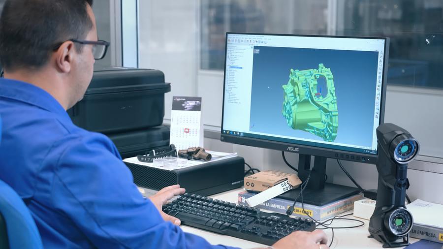
The measurement method depends on the geometry and required accuracy. Not every component needs 3D scanning.For relatively simple metal parts, calipers, micrometers, height gauges and thread gauges may be sufficient. Coordinate measuring machines can be used when hole positions or other geometric relationships require more accurate measurement.For complex curves, irregular cast surfaces and features distributed across several planes, 3D scanning can capture the overall surface geometry and reduce the amount of manual measurement required.However, scan data should not automatically be treated as the final machining model. Surface reflections, hidden areas, scanning accuracy and data processing can all affect the results.Critical features such as bores, threads and locating surfaces still need to be checked separately.A practical approach is to use scanning for the overall shape and precision measurement for critical dimensions. Combining the two methods can provide a more reliable basis for model reconstruction.
Once the measurements are available, they need to be converted into a CAD model and manufacturing drawing.Simple plates, brackets and bushings can often be modeled directly from measured dimensions. Complex castings and curved components may require point-cloud processing, surface fitting and solid modeling.
Several details need to be considered during this stage.First, the model must include more than the external shape. Hole positions, locating surfaces, mating dimensions and required tolerances need to be defined.Second, the model should reflect the intended manufacturing process. A hole represented in a 3D model may still require drilling, boring or reaming. Tool access, workholding and machining allowance must be considered.Third, cast surfaces and finished machining surfaces should be distinguished. A casting's raw dimensions are not necessarily the same as its final machined dimensions.Material grade, heat treatment and surface finish should also be specified when these requirements are known. Otherwise, a replacement may match the original dimensions but fail to meet the required strength, wear resistance or corrosion resistance.
After the drawing is completed, the manufacturing process can be selected according to the part's geometry, material and order quantity.CNC machining may be suitable for simple parts and small batches. For more complex shapes or larger production quantities, casting followed by CNC finish machining may be worth evaluating.
The final choice depends on the required tolerances, surface finish, material and total cost.Where the part must fit existing equipment, producing a trial part and checking the actual assembly is recommended whenever practical.Inspection requirements depend on the application. A bracket may require checks of hole spacing and mounting position. A bushing may require bore, outside-diameter and fit inspection. A flange may need checks of hole locations and mating faces. A cast valve body may require dimensional inspection and appropriate pressure or leakage testing based on its operating conditions.If the trial part does not fit, the measurement data, datum selection and CAD model should be reviewed before making adjustments.Once the part has passed the required checks, the approved drawing, material specification and inspection requirements can be used for repeat production.
Reverse engineering cannot recover every detail from external measurements alone.
A component may contain internal oil passages, cooling channels or cavities that cannot be inspected from the outside.
Parts used in high-load, high-speed, pressure-containing or safety-critical applications may also require material verification, heat-treatment information, fatigue assessment or additional testing. Similar dimensions do not automatically make two parts interchangeable.
If the original part is severely damaged, equipment documentation, mating components, technical manuals or another part of the same model may be needed to establish the correct design.
These uncertainties should be identified before quotation and production rather than treated as confirmed specifications.
For metal parts without original drawings, HAOZHIFENG can help assess the feasibility of measurement, CAD reconstruction and subsequent manufacturing based on the information available.
Customers can start by providing:
• Clear photos of the part from different angles;
• Main dimensions, hole diameters and hole spacing;
• Material and surface finish requirements, if known;
• The part's installation position and application;
• Required quantity and expected repeat-order demand.
A physical sample or relevant mating component can also help clarify critical dimensions and assembly requirements.
For complex parts or applications with tight tolerances, the available information should be reviewed first to determine whether 3D scanning, precision measurement or additional engineering analysis is necessary.
If you need to reproduce a metal component but no longer have its original CAD files, contact HAOZHIFENG with the available sample or dimensional information to discuss a suitable manufacturing approach.